Getting Started |
您所在的位置:网站首页 › curtain motor terminal › Getting Started |
Getting Started
|
Getting Started Prerequisites~ Needed Hardware~
Every Espressif ESP8266, ESP8285, ESP32, ESP32-S or ESP32-C3 chipset based device can be flashed with Tasmota. The term ESP refers to any of them. Serial Programmer~The power supplied to the device is one of the most important elements for both flashing the device and for stable operation. You must ensure that the device receives sufficient power (current AND appropriate voltage level) to properly flash the firmware on the device. RECOMMENDED CH340G is the most reliable and the cheapest one to boot (CH340G, Sparkfun, Soldered Connect, CH340N with AMS1117). RECOMMENDED VoltLink - USB to serial adapter board based on the popular CP2102N chip with built-in ESP auto-reset circuitry and a 500mA voltage regulator CP2102 or PL2303 - works with certain devices, but using an external 3.3V supply might be necessary. Not recommended for beginners! NodeMCU You can also use a NodeMCU (or similar) as a reliable serial programmer if you disable the onboard ESP by bridging GND to the RST or EN pin, and connect TX and RX straight to another ESP82xx instead of crossed. RECOMMENDED VoltLink - USB to serial adapter board based on the popular CP2102N chip with built-in ESP auto-reset circuitry and a 500mA voltage regulator CP2102 or PL2303 - works with certain devices, but using an external 3.3V supply might be necessary. Not recommended for beginners! NodeMCU You can also use a NodeMCU (or similar) as a reliable serial programmer if you disable the onboard ESP by bridging GND to the RST or EN pin, and connect TX and RX straight to another ESP82xx instead of crossed. Don't forget to install drivers for your serial programmer. Danger Some adapters can be switched between 3.3V and 5V for the data pins, but still provide 5V on the power pin which will irreparably destroy your device. You MUST make sure the data (RX and TX) and VCC pins are set for 3.3V.
When using an external 3.3V supply, ensure the ground (GND) of both are connected together, this ensures a common ground. A PC power supply can be a source for 3.3V DC power. Devices with an USB upload port typically have a serial programmer built in, such as NodeMCU, D1 mini or M5Stack products. Soldering Tools~To solder you'll of course need a soldering iron, soldering tin and some flux. If you're new to soldering check out some soldering tutorial videos while you're at it. If you're intimidated by soldering there are 3D printed jigs available for different modules and devices. At worst, you could get away with holding the headers tightly with jumper wires in pin holes during flashing but it is not a foolproof process and flashing might fail. Jumper Wires~You could use any kind of wire but jumper wires (also called DuPont wires) are more practical than soldering and desoldering. Pin Headers~
Pin headers come in male or female version. Choose according to your jumper wire connectors. Computer with Linux, Windows or MacOS~You need a computer with a USB port to upload the firmware to your device and configure it. Smartphone~Tasmota installed from a precompiled binary needs to be configured to work with your Wi-Fi network before you can access the Tasmota web UI. This is usually done by connecting to a Tasmota Wi-Fi Access Point with your smartphone (or tablet or computer with Wi-Fi). Needed Software~ Tasmota Firmware Binary~Download a Tasmota firmware binary file (.bin). If you're not sure which binary is the right one for you just start with tasmota.bin or consult the builds table to see which features you need. Official release binaries can be downloaded from firmware server. Latest development branch binaries are available only from our OTA server. The latest merged development code is compiled hourly. Flashing Tool~ Tasmota Web Installer - flash Tasmota using a Chrome based browser for ESP82XX and ESP32 Tasmotizer - flashing and firmware download tool for ESP82XX only. (Windows, Linux or Mac) ESP-Flasher - GUI flasher for Tasmota based on esptool.py for ESP82XX and ESP32. (Windows, Linux or Mac) Esptool.py - the official flashing tool from Espressif for ESP82XX and ESP32. Compiling Tools (optional)If you want to modify the code or default settings and compile your own Tasmota firmware. MQTT Knowledge~Tasmota is designed to be controlled and communicate via MQTT. To use it to its fullest potential you need an MQTT broker. Read our article on MQTT to learn why it is essential in Tasmota. Hardware Preparation~We need to connect to the serial programming interface of the ESP chip. This is done by connecting our serial-to-USB converter TX and RX pins to the ESP RX and TX pins and powering the chip with the 3.3V and GND pins. In most cases those pins are available on the PCB in the form of pin holes or solder pads but pin headers or jumper wires need to be soldered or otherwise applied. In some cases you will need to solder wires directly on the chip's pins which requires some experience and good soldering equipment. DO NOT CONNECT DEVICES TO MAINS AC POWER WHILE THE COVER IS OPEN AND CIRCUIT BOARD IS EXPOSED!!!
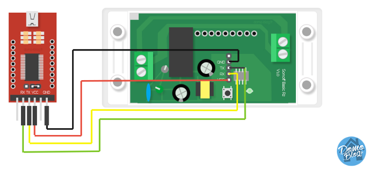
NEVER TRY TO FLASH WHILE YOUR DEVICE IS CONNECTED TO MAINS POWER!!! YOU CAN BE ELECTROCUTED IF YOU DO NOT KNOW WHAT YOU ARE DOING! If you are not careful, your own health will be in danger. Shorting your serial interface with mains AC power will fry your device and serial adapter and will also harm or destroy your computer. It is important to always have all mains power cables disconnected from the device while being connected via serial or even while the case of the device is opened. Serial Connection~Each device has its pins labelled differently. If the labelling isn't visible on the PCB please refer to the devices flashing guide or search the Internet for correct pin locations. Device specific instructions and restrictions are documented in the Tasmota Supported Devices Repository. Pinouts for commonly used Wi-Fi modules are found here When you have identified pins on your device, connect wires according to the table: Serial adapter ESP device 3V3 3V3 or VCC TX RX RX TX GND GNDNote that TX from your adapter goes to RX on the ESP device and RX from adapter goes to TX on the device!
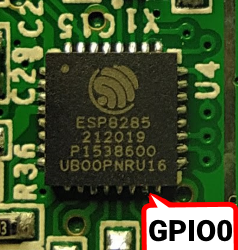
ESP needs to be put into programming mode or flash mode before the firmware can be uploaded. This is done by connecting GPIO0 pin to GND while the chip is booting. On many devices the installed control button is connected to GPIO0 and GND, making entering Programming Mode easy. On others you will need to bridge the pins on the PCB or directly on the chip with a jumper wire. GPIO0 locations for popular modules can be found in Pinouts! Device specific instructions are documented in Tasmota Supported Devices Repository. To put the ESP into Programming Mode: Disconnect serial programmer and power Bridge GPIO0 and GND (by pressing the on-board button or connection with a wire) Connect the serial programmer to your computer After a few seconds disconnect GPIO0 from GND (release button or remove the wire connection). On devices that do not provide the GPIO0 connected button, it may be easier to leave the wired bridge in place throughout the entire flashing process (erase & upload). Doing so will not create any problems. After the firmware is uploaded successfully, remove the bridge. This allows the device to boot normally. esptool.py programming mode testYou can test whether your device is in Programming Mode by attempting to read information from the ESP82xx chip. This requires esptool.py. Instructions on installing and using esptool are provided below. For example (COM5 will be your COM port): esptool.py -p COM5 read_mac (It should read the MAC address. It may fail afterwards during Uploading and running a "stub". This is normal.) esptool.py -p COM5 flash_idIf everything went well, you are now in Programming Mode and ready to continue with flashing. If the flashing process is unable to start, disconnect the device and retry the steps. Common Mistakes~ Wire connections and solder joints - Double check all connections and also check for solder overflow. Use a USB data cable - Some USB cables are for charging only and do not connect the data lines needed to load the firmware onto the device. Insufficient power delivered over the serial programmer. This leads to flashing failures or corrupted flash altogether. Supply more power with a separate 3.3V power supply or get an adapter with a better power supply. Be sure all DC voltages use the same GND line. Recheck your serial programmer so to ensure that it supplies 3.3V voltage and NOT 5V. 5V will damage the ESP chip! Releasing GPIO0 button/wire before booting is finished - It is safe to leave GPIO0 connected to GND during the entire programming process (erase & upload). Just be sure to remove the GPIO0 to GND bridge before booting the device for regular operation. Make sure that the RX pin is connected to the TX pin between the serial adapter and your ESP device, and vice versa. Note: some devices can have the TX and RX pins labelled in reverse. In that case connect TX to TX and RX to RX pins of your adapter. Erase the flash first and power cycle before uploading the Tasmota firmware binary. Not erasing can leave behind remnants of the previous flash contents which can interfere with the new firmware operation. Flashing~If you have followed Hardware preparation, your device should be in Programming Mode and ready for a Tasmota firmware binary to be installed. You may want to back up the device manufacturer's firmware on the one in a million chance you don't like Tasmota.
Choose an installation method: Flash Tasmota directly from your web browser. Tasmotizer! is specifically designed for use with Tasmota with an easy to use GUI and esptool.py under the hood. for ESP82XX onlyDownload the latest release for your platform. In Windows just double click the downloaded file and it'll start, no installation required. For python follow the installation instructions. Note If you get an anti-virus infection warning don't fret, it is a known false positive. If you're still apprehensive you can always run the Python version. It is time to Tasmotize!
Danger Leave Erase before flashing checked if it is the first time flashing Tasmota on the device or you're experiencing issues with the existing flash and need to do a full erase. If you're upgrading an already flashed Tasmota and wish to keep your settings, uncheck Erase before flashing. Click Tasmotize and wait until done.
If the flash was successful it will display:
Unplug your serial programming adapter or device and plug it back in or connect to another power source. Esptool is the official Espressif tool for flashing ESP chips. It requires Python, if you do not have an installed copy of Python 2.x or 3.x download and install it from https://www.python.org. Use Esptool packaged with your distro or install it yourself with command: pip install esptool Old esptool versions will not detect and will not flash newer chips (ESP32-C3, ESP32-S3, etc)Make sure you followed the steps to put your device in Programming mode. Place your chosen firmware binary file in the current folder you run esptool.py from. Esptool uses the serial interface to communicate with your device. On Windows these interfaces are named COM1, COM2, etc. and on Linux they are named /dev/ttyUSB0, /dev/ttyUSB1, etc. Before using esptool, make sure you know which serial port your programming adapter is connected to. The following use COM5 as an example. Change COM5 with your serial port designation. Ensure the device is in programming mode before each step. Backup Firmware (optional step)~Backup the current firmware with the following command: esptool.py --port COM5 read_flash 0x00000 0x100000 fwbackup.bin When the command completes the device is not in programming mode anymore. Repeat the process of putting your device in programming mode. Erase Flash Memory~Erase the complete flash memory holding the firmware with the following command: esptool.py --port COM5 erase_flash It only takes a few seconds to erase 1M of flash.When the command completes the device is not in programming mode anymore. Repeat the process of putting your device in programming mode. Upload Firmware~Load the chosen Tasmota firmware file with the following command (e.g., tasmota.bin in this example): esptool.py write_flash -fm dout 0x0 tasmota.bin or for ESP32:Note Factory binaries are used for inital flashing this time https://ota.tasmota.com/tasmota32/release/ esptool.py write_flash 0x0 tasmota32.factory.binUnplug your serial programming adapter or your device and plug it back in or connect to another power source. Your device is now ready for Initial configuration. For proper device initialization after the firmware upload completes, power down and power up the device. Tasmota is NOT a developer of these tools. For help and troubleshooting you will need to get support from those projects. MgOS to Tasmota - OTA flash for Shelly devices MgOS32 to Tasmota32 - OTA flash for Shelly Plus and Pro (ESP32) devices Tuya-Convert - OTA flash for devices with Tuya chips. Does not work in 99% of cases Sonoff DIY - OTA flash for select Sonoff devices Does not work anymore esp2ino - OTA flash for select Wyze devices. Does not work anymore Initial Configuration~
Tasmota provides a wireless access point for easy Wi-Fi configuration.
When it connects to the network, you may get a warning that there is no Internet connection and be prompted to connect to a different network. Do not allow the mobile device to select a different network. Warning Wi-Fi manager server is active for only 3 minutes. If you miss the window you might have to disconnect your device from power and reconnect.
WiFi Network - your Wi-Fi network name (SSID Selecting the desired network name from the list will enter it automatically in this field. SSID's are case sensitive WiFi Password - password for your Wi-Fi network Wi-Fi password has to be under 64 characters and without special characters (e.g. asterisks) or white spaces Click the checkbox if you want to see the password you enter to ensure that it is correct. Click on Save to apply the settings. The device will try to connect to the network entered.
If it was successful, you will see this message:
Some phones will redirect you to the new IP immediately, on others you need to click the link to open it in a browser. The tasmota_XXXXXX-#### network will no longer be present. Therefore your smartphone will automatically be disconnected and should connect back to its data network. Failure  In case the network name or password were entered incorrectly, or it didn't manage to connect for some other reason, Tasmota will return to the "Wi-Fi parameters" screen with an error message. In case the network name or password were entered incorrectly, or it didn't manage to connect for some other reason, Tasmota will return to the "Wi-Fi parameters" screen with an error message.
If you don't know the IP of the newly flashed device look in your router settings or find it with an IP scanner: Fing - for Android or iOS Angry IP Scanner - open source for Linux, Windows and Mac. Requires Java. Super Scan - Windows only (free)Open the IP address with your web browser and you have full access to Tasmota. Now is the time to set up MQTT and the last remaining, but equally important, step: Set up your device's feature using a Template in Configuration - Configure Template or Module in Configuration - Configure Module. Configure Other (optional) Configure your device name which is displayed in webUI and used for Home Assistant discovery. Configure web admin password for the webUI. Default username is admin. This type of security is rudimentary since Tasmota doesn't use HTTPS, do not expose your device outside of your local network. If you flashed the device using serial programmer (or it is a NodeMCU/D1 mini) you can take advantage of the existing connection and configure your device over the serial connection using Commands. First you will need a serial terminal program that connects to Tasmota console over the serial connection you used to flash it. Termite - simple terminal for windows Termie - open source clone of Termite Putty - popular client available on every platform Minicom - one of many Linux terminalsTip Enable local echo so that you can see what is typed and transmitted to the device. Enable Append CR+LF since every request needs to end with . In this example Termite on Windows is used. Download Termite and extract the .exe file, no installation necessary. Connect your serial programmer or NodeMCU/D1 mini to the computer.
Open Termite and set it to the proper COM port (Termite selects the first available port by default). Set Baud rate to 115200 and Forward to none.
Connect your device to the serial programmer. You should see the initial boot output in Termite. If your screen is empty type status in the bottom command bar and hit enter. If you get a return message from your device similar to the one displayed under purple status you're all set. To configure Tasmota you need to issue commands, some commands will reboot your device and to avoid that we will use the Backlog command feature. Configure your Wi-Fi network and a secondary Wi-Fi network Backlog ssid1 ; password1 ; ssid2 ; password2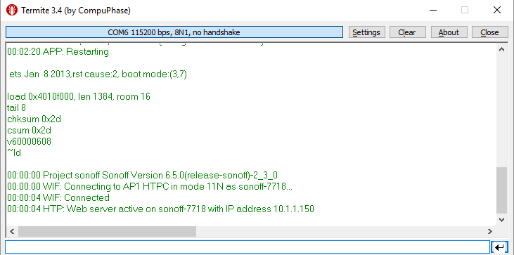 Device will restart and connect to your network. It will display your devices newly assigned IP. Direct your web browser to that IP address to access the Web UI for further configuration and control. Configure MQTT broker address, MQTT credentials, unique device topic and OTA url to the latest official release Backlog mqtthost ; mqttuser ; mqttpassword ; topic ; otaurl http://ota.tasmota.com/tasmota/release/tasmota.binCommands and Backlog are powerful and in time you can learn to configure almost everything (NTP servers, longitude and latitude, custom device options, etc) with a few copy and paste moves. Tip Keep your personal configuration in a text file and simply copy and paste the backlog commands to a newly flashed device. After Configuration~Your device running Tasmota is now ready to be controlled. Check out all the Tasmota features and ways to integrate it with other platforms. Warning If you experience power fluctuations in your power grid it's best to immediately disable Power Cycle Recovery feature with command SetOption65 1 immediately or you might end up with firmware defaults on your device. |

 Many serial programmers do not have a voltage regulator on board like the pictured ones. The ESP requires at least 150mA, many 3.3V serial programmers cannot supply this much current as many serial programming tasks do not require a large amount of power.


 Once the installation is successful, click on NEXT. The installer will scan for Wi-Fi networks and select the strongest one. Use the dropdown to select between networks.
 Enter the Wi-Fi password.
 Wait until configuration completes and click CONTINUE
  From here click on VISIT DEVICE to enter the WebUI for further configuration.
 Connect your device to a power source and grab your smartphone (or tablet or laptop or any other web and Wi-Fi capable device). Search for a Wi-Fi AP named tasmota_XXXXXX-#### (where XXXXXX is a string derived from the device's MAC address and #### is a number) and connect to it. In this example the Wi-Fi AP is named tasmota_3D5E26-7718.
  After you have connected to the Tasmota Wi-Fi AP, open http://192.168.4.1 in a web browser on the smartphone (or whatever device you used). Depending on the phone, it will take you to the Tasmota configuration page automatically, or you will get a prompt to sign in to Wi-Fi network or authorize. Tapping on the AP name should also open the configuration page.
 At the top of the page you can select one of the discovered Wi-Fi networks or have Tasmota scan again. Enter your WiFi credentials:


【本文地址】